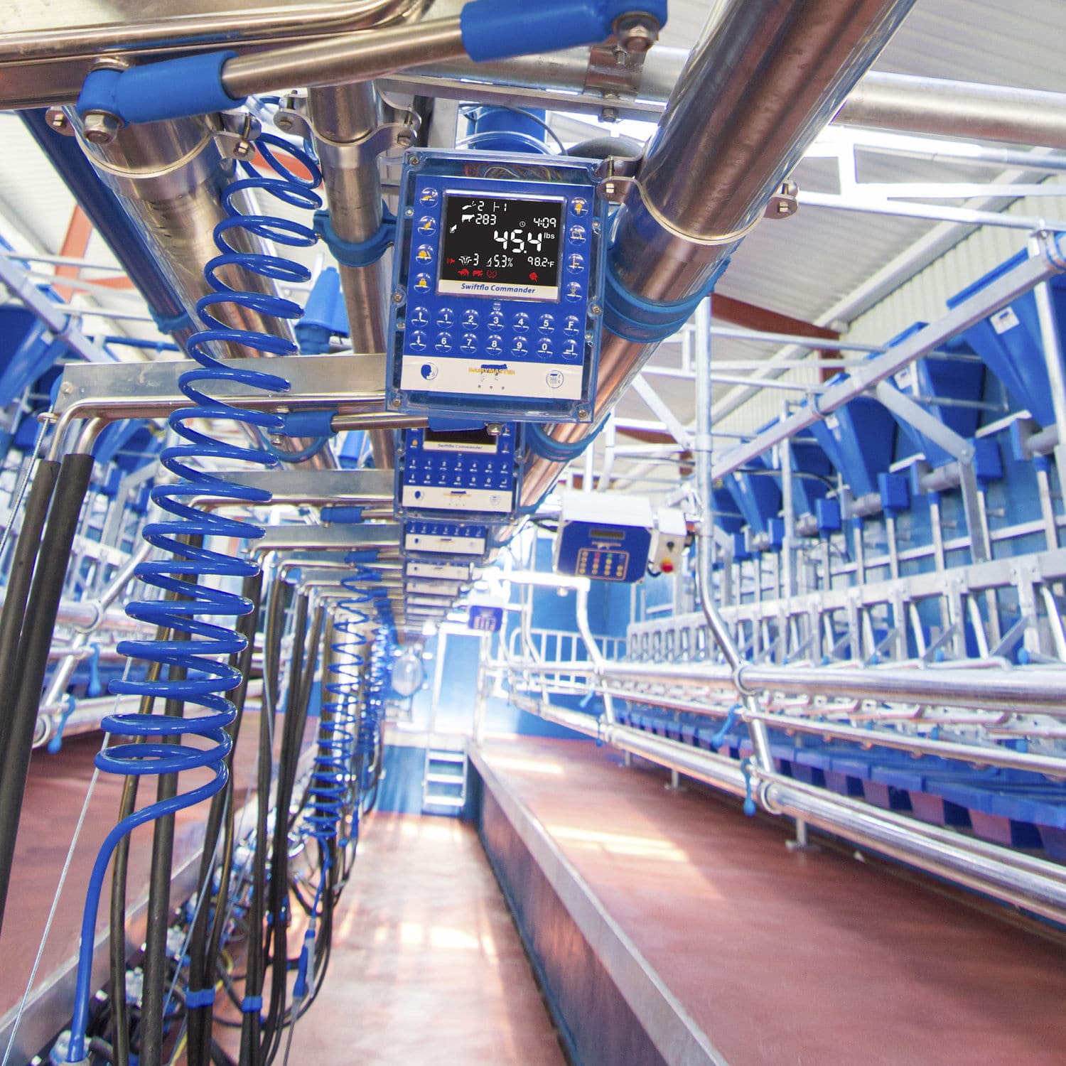
The most important aspect concerning the efficient functioning of milking machine systems is vacuum stability. It is associated with positive milk removal from the udder with minimum irritation for the cow.
Factors that play an important role are:
Presence of milk bottles
The presence of a milk bottle creates a vacuum reserve that suppresses vacuum fluctuations and therefore reduces udder damage and mastitis.
Position of weighing bottles
It is important that the bottle is as close as possible to the cow’s udder, and as close possible to the same level.
Obstructions in the milk-flow path
Any obstruction such as joints in milk tubes, must be avoided. It causes turbulence and the milk becomes rancid.
Pipeline height and length
The milk tube must be as short as possible, have as few turns as possible and may not rise vertically while it is under a vacuum. The milking parlour must therefore be on a higher level than the milk room. After the milk is separated, that is at atmospheric pressure, it may be pumped to a cooling unit.
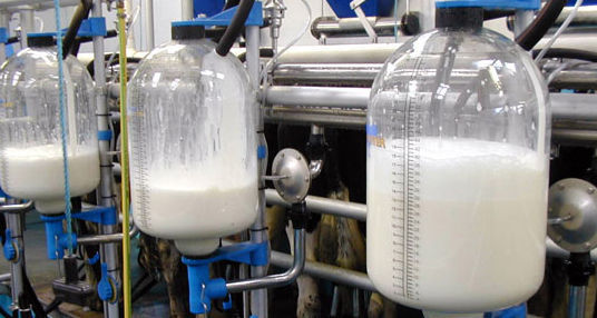
With the help of milking jars, fluctuations in pressure are reduced. (Image: Agriexpo.online)
Norms, sequence sizes and requirements in the planning of a milking machine system
Vacuum provision
- The vacuum pump size must deliver a minimum of 100 m3/min free air per milking unit, therefore a 4-point tandem system must be 400 m3/min.
- 100 m3/ min free air gives 200 m3/min expelled air.
- The airflow capacity of a vacuum pump drops with 4% for each 300 m rise above sea level.
- A maximum of eight elbows in the vacuum line between the vacuum pump and first milking point must be allowed.
- There must be zero constrictions in a vacuum line between the vacuum pump and the first milking point.
- The reserve airflow must be 40% of the pump capacity or higher.
- The restoration time must be less than four seconds.
- Airflow consumption per milking unit is 40 m3/min free air.
- Airflow loss resulting from the vacuum supply line must be less than 30%.
- V-belt tension must be correct.
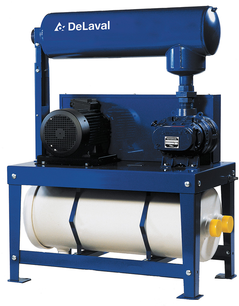
A vacuum pump. (Image: Northstardairy.com)
Vacuum control
- Conventional vacuum level during milking is 44 to 50 kPa.
- Bio-milker must be – 42 kPa.
- 50 kPa equals 380 mm Hg (mercury).
- The vacuum level during wash action can be higher than 50 kPa.
- The vacuum meter reading must correlate with the vacuum level that prevails right above the measuring beaker or flow meter.
Pulsation
- Pulse tempo: 50 to 60 (pulse tempos between pulsators in the zasame parlour may not differ with more than two pulses per minute both sides of the manufacturer’s specifications).
- Milk/rest relation: 50:50 to 70:30 (milk/rest relation between pulsators in the same parlour may not differ with more than 4% both sides of the manufacturer’s specifications).
- Air flow consumption – pneumatic: 30 m3/min; electronic: 20 m3/min.
- When the pulsator lets in air, the vacuum between the teat sheath and the teat head must lapse completely (0 kPa).
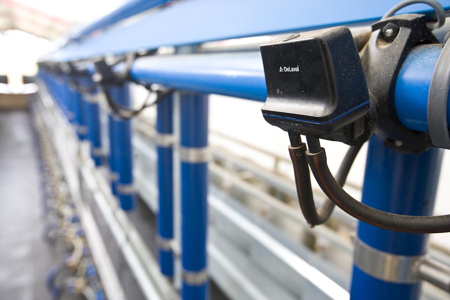
Positioning of a pulsator. (Image: Dairycare.co.za)
Milk tube
- Milk tubes must be as straight and short as possible.
- Elbows in a horizontal level must be limited as far as possible.
- Subsiding pieces must be avoided as far as possible.
- Rising pieces must be eliminated at all cost.
- The grade of the milk tube must be even and inclined in the direction of the milk jar (1:60 to 1:100).
- For better wash action, the milk tube must be installed lower than the measuring flask.
- The milk conveyor tube must join in the top third of the milk tube.
- The milk tube diameter must be large enough to prevent overflowing, but small enough to ensure effective wash action.
- No air may be sucked in after the milk, for instance, when a measuring flask is being emptied.
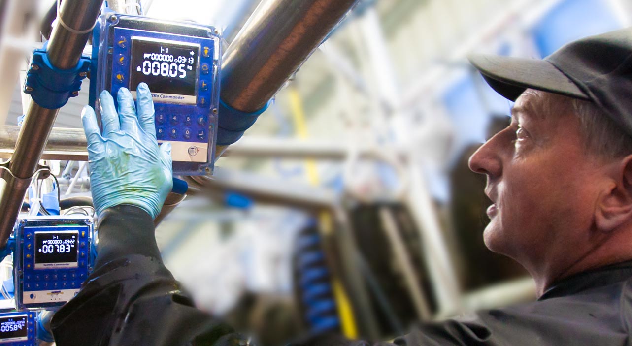
Milk vacuum stability
- The milk vacuum variance may not exceed the norm of 10 kPa.
- Requirements for a good milk vacuum stability:
- Large enough vacuum pump for sufficient reserve air flow.
- A low installed measuring flask, flow meter or pipeline.
- Short milk tubes (shorter than 1,5 m).
- No flow limitations in milk tubes.
- Open air bleeding openings in the claw pieces.
- An equal milk tube inclined in the direction of the milk jar.
- No air leakage may occur in any part of the milking unit or measuring flask.
Milking robots
Milking robots improve the lifestyle of the producer, as well as that of the cow (Mottram & Cooper, 1999). After years of uncertainty and scepticism, dairy farmers worldwide are considering milking robots as replacements for labourers. It seems that initial errors with the milking robots have been solved with improved technology that results in more dependable systems.
The milking parlour in which the robot is used, consists of three parts. In the first part, cows are fed after being milked. From there they move to the second part to rest. A one-way gate prevents them from returning to the feeding troughs. They are therefore forced to move to the third part, namely the milking robot, when they are hungry (Van Rooyen, 1998).
A computer controls movement between the resting area, the parlour, and the feeding area by using automatic identification and automatic drafting gates. A cow cannot move from the resting area to the feeding area without going through a series of drafting gates. The computer determines whether the cow has just been milked or has just been in the feeding area. If that happens, her entry is blocked, and she remains in the resting area. Cows leaving the milking robot are drafted to the feeding area by another automatic drafting gate, which is also used for drafting sick cows or cows that must be examined (Field, 1999).
The milking process begins when the cow enters the parlour. A computer identifies the cow by means of an electronic identification disc worn by the cow and determines whether the cow should be milked. If needed, the cow enters the milking crate where a computerised feeding station makes a certain amount of fodder available to the cow.
The cow’s udder and teats are now washed by a washing device mounted on a metal arm on rollers. When the udder is washed, the metal arm retracts, after which the positions of the teats are determined by a laser device. The laser device communicates with the arm containing the teat heads which allows the arm to couple the teat heads with the teats at exactly the correct position.
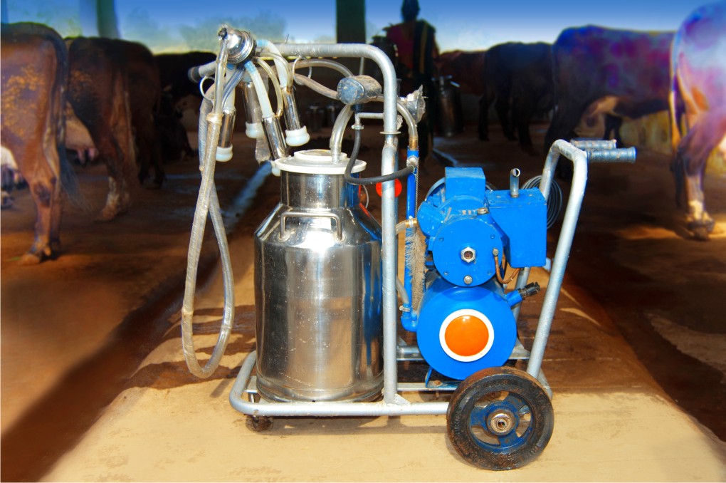
A milking unit for a small-scale farmer. (Image: Kisaanji.com)
Each teat is milked separately. As soon as one quarter of a teat is milked, that teat head is disconnected. The other teat heads keep milking the cow until all four quarters are milked out. Better udder health is obtained this way. The first bit of milk from the teat is prevented from entering the storage tank by an automatic valve in the milk line. Milk that comes from the udder after that is clean and goes to the storage tank.
When the cow has been milked, her teats are sprayed with a disinfectant before she leaves the crate. As soon as all the teat heads are removed, the arm moves away from the cow and each teat head is then washed with a sprayer unit. Cross-infection between cows is prevented this way.
All milking equipment are standard. The only addition to a robot system is the robot-arm.
The manufacturers recommend that four crates are installed, served by one robot. The robot moves on rails by itself from one crate to another to milk the cows. The most important benefit of this type of system is the saving in labour costs.
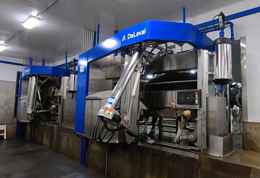
A modern milking robot. (Image: DeLaval.com)
Automated milking does however not only show a saving in labour costs, but building costs are lower because of the smaller feeding and holding area. Over and above the labour costs, the running costs of the milking equipment at automated and conventional systems must be compared and, more important, the actual cost of milking must be considered.
Often, the conventional milking process will be more expensive.
A further benefit of automated milking systems is that cows can be milked 24 hours a day. Because cows can be milked more times per day (up to four times), it results in an increase in milk yields of 15%. According to Murray (1999), there are exciting times ahead for automated milking systems, as they are a viable alternative to conventional systems.
Published with acknowledgement to the ARC Agricultural Engineering for the use of their manuals. Visit www.arc.agric.za for more information.

